11 Parts Of Car Starter Motor And Function
Starter motor components – engine starting system is a
system that have a function to crank the engine for the first time. The working
principle of starter motor is to rotate the engine crankshaft via flywheel
using electric motor circuit. The result is a rotating crank and engine cycle
can be triggered to work continuously.
In this article, we will learn all about parts of starter
motor and their function. Check the article below.
All Parts Of Starter Motor and function

img by jcrsupplies.co.uk
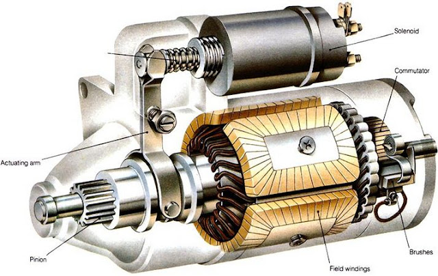
1. Solenoid starter
The first component you can see on the part that looks like
a small tubular part on the main motor. This component is named solenoid
starter because it contains two solenoid. The main function of Solenoid starter
is to push the pinnion drive gear and give voltage on main motor.
There are two solenoid in this component namely;
- Pull in coil, this component works to push the plunger to push the drive pinion gear.
- Hold in coil, is a similar component located in front of the pull in coil. Its function is to withstand the movement of the pull in coil and connect the battery current to the main motor.
The shape of the solenoid is like a coil, where an iron core
is placed in the middle of a copper coil. But this winding has a large number
and the dimensions are also larger so as to move the plunger with a strong and
fast.
2. Solenoid plunger

The plunger is located at the end of the pull in coil. Its
function is only one that connects the movement of pull in coil to drive lever.
In other words, this component only acts as a connecting rod. However, this
plunger material is also strong because it will connect the pull in coil pull
that have strong movement.
3. Solenoid cap
The solenoid lid is a starter solenoid cover circuit located
on the front of the starter. Not only as a cover, but this part is also used as
a media liaison between the current from the system to the starter actuator.
Actually there are 3 pieces of terminal on the starter motor ie
- Terminal 50, is a terminal connected to the starter circuit of the ignition key. Through this terminal the starter motor gets the command to active or not. When terminal 50 gets current then the solenoid will work and the starter will react.
- Terminal 30, the terminal which directly gets the electric current from the battery. In other words electric current is always available at this terminal when the motor is off or on.
- Terminal C, the terminal used to channel the main currents from the solenoid to the starter motor in order to rotate. It will connect the current from terminal 30 when terminal 50 gets current.
4. Field Coil
We go to inside the motor starter, here there are many
components that you can find. First you can find the field coil. What is a
field coil? field coil is a series of magnetic coils used to generate magnetism
around the coil rotor. According to the working principle of an electric motor
that requires a magnetic field around the rotor, this component will provide
it.
But the coil field is not a permanent magnet, the field coil
will only generate a magnet if there is a current input from terminal 50. This
process we usually call the process of electromagnetic induction. The field
coil is also consists of several parts such as
Yoke, is the housing where the coil is located. In this case
the coil lies inside the yoke.
Pole core, is a flat iron core which is used as a place of
welding of copper to become a coil.
This coil is made of ordinary copper coils make with a
certain direction around the pole core, in the yoke there are about 4 to 6
units of pole cores are interconnected to obtain great magnetism.
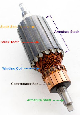
5. Armature coil
The next component, inside of starter motor, it is commonly
referred to as a coil rotor or coil located around the motor shaft. The main
function of the armature coil is also as a magnetic field generator that will
be reacted with magnet field coil for the occurrence of movement.
The shape of armature coil such as rotor that hav tubular
shape. In general it is coated by copper, the difference with field coil, can
be find in its dimmension and amount of coopers. Armature coil has a large
number of windings and the amount of coopers also quite large, so the diameter
of the coil is also larger.
6. Commutators

img by groschoop.com
The next component, located on the front of the armature
coil, it shaped like a segmented copper plate. The function of the commutator
is to connect the electrical current from the brush to the armature coil. The
segmented form of commutator prevents short circuiting of electric current
because in the process the commutator will be connected to positive and
negative currents directly.
7. Drive lever / Actuator shaft
We go back into the solenoid, here there is a fork-shaped
component that serves to move the pinion gear. The drive lever works with the
principle of the lever, which will bring up the pinion gear when the other end
is pushed in opposite directions. Who is pushing? this is a function of pull in
coil through plunger. While the other end will make the pinion gear pushed out and
connected with flywheel.
8. Brushes
The next component lies on the main motor. Here is a series
of brushes used to connect the electrical current from a static conductor to a
dynamic conductor. That is, this brush will send an electric current from
terminal 50 to the armature coil that moves around through the commutator.
In a starter motor, there are usually about 4 or more
brushes with two as a positive brush and the other two as negative brushes. The
material of this brush is also made of copper but softer, to keep the
commutator from wearing out. But, the impact brush become more quickly wear
out. If this happens then the starter will be difficult to run.
9. Drive Pinnion Clutch
The next component, we will encounter a mechanical clutch
that has function to connecting and disconnecting rotation from the starter
shaft to the flywheel. Why the rotation need to be disconnected? it is because
the stater motor is unlikely to keep working when the engine is running. So in
a normal condition, the starter will be connected and when the starter system
is turned on the round starter will be connected with flywheel.
How to work this clutch that is by utilizing slide gear with
tilt model. this is because there is an overlap clutch component located at the
end of the pinion drive. When the starter system is turned on then the drive
lever will push this clutch, but with the angled slide gear then the pinion
drive will move out while rotating beyond the starter spin.
This is intended for pinion to be fast and perfect timming
connection with a flywheel gear. In the reduction strater type, this coupling
component gets an additional part that is used as a rotary reducing gear, the
goal is that moment on pinnion gear becomes bigger.
10. Drive pinnion gear
The next component is shaped like a gear in general that is
located at the end of the drive pinion shaft. The function of this pinnion gear
is to connect the rotation of the generated electric motor to the engine
crankshaft via flywheel. The pinnion diameter is quite small compared to the
flywheel so it will increase the gear ratio that makes the starter system
capable to rotate high capacity engine.
11. Motor housing

The last part is housing, which has the function as a
protective part and as a place to put various components of starter. This
housing is made of metal consisting of tubular main housing, pinion housing as
pinion gear and stamped in front of the main housing as a starter chassis
cover.
Thus the full article and clear about the parts of the
starter motor and their functions on cars and motorcycles. Hope can increase
our insight and benefit us all.


